วันพุธที่ 21 มิถุนายน พ.ศ. 2560

NI labview 2014

NI labview 2014


โปรแกรม LabVIEW ย่อมาจาก Laboratory Virtual Instrument Engineering Workbench โปรแกรมที่ พัฒนาขึ้นมาโดยใช้ LABVIEW จะเรียกว่า Virtual Instrument หรือจะเรียกยอ่ ๆ ว่า VI ซึ่งหมายถึง เครื่องมือวัดเสมือนดังตัวอย่าง จากรูปนี้เป็น Oscilloscope ที่ได้ทำ การสร้างขึ้นบนหน้าจอคอมพิวเตอร์

LabVIEW อาศัยหลักการทำงานของเครื่องมือวัดหรือการวัดคุมทำให้ผู้ใช้สามารถออกแบบตามที่ผู้ใช้ต้องการ หลักการดังกล่าวแบ่งออกเป็น 3 ส่วนใหญ่ๆ คือ


ส่วนประกอบต่างๆ ใน LabVIEW โปรแกรมที่เขียนขึ้นมาโดย LabVIEW เราจะเรียกว่า Virtual Instrument (VI) เพราะ ลักษณะที่ปรากฏทางจอภาพเมื่อผู้ใช้งานจะเหมือนกับเครื่องมือหรืออุปกรณ์ทางวิศวกรรมใน ขณะเดียวกันหลังฉากของอุปกรณ์เสมือนจริงเหล่านั้นจะเป็นการทำงานของ ฟังก์ชันSubroutines และโปรแกรมหลัก เหมือนกับ ภาษาทั่วไป จะประกอบดว้ยส่วนประกอบ 3ส่วน คือ
1 Front Panel นี้จะเปรียบเสมือนเป็น GUI ของโปรแกรมหรือ VI นั่นเอง


เครื่องมือที่ใช้ออกแบบ Front Panel
-         Controls Palette
-         Tools Palette


2 Block Diagram Block Diagram จะประกอบดว้ย ฟังก์ชันค่าคงที่โปรแกรมควบคุมการทำงานหรือโครงสร้าง จากนั้นในแต่ละส่วนเหล่านี้ซึ่งจะปรากฏในรูปของ Block เราจะได้รับ การต่อสาย (Wire) สำหรับ Block ที่เหมาะสมเข้าด้วยกนั้นเพื่อกำหนดลกัษณะการไหลของขอ้มูล ระหว่าง Block เหล่านั้นทำให้ข้อมูลได้รับการประมวลผลตามที่ตอ้งการและแสดงผลออกมาให้แก่ผู้ใช้งานต่อไป


3 Icon และ Connector เปรียบเสมือนโปรแกรมย่อย Subroutine ในโปรแกรมปกติทั่วๆ ไป โดย Icon จะหมายถึง Block Diagram ตัวหนึ่งที่มีการส่งขอ้มูลเข้าและออกผ่านทาง Connector ซึ่ง ใน LabVIEW เราจะเรียก Subroutine นี้ว่า “SubVI”


ติดตั้ง LabVIEW 2014
1.       Install LabVIEW 2014 โดยติดตั้ง กด Next ไปเรื่อยๆ โดยติดตั้งสมบูรณ์จะได้หน้าตาแบบนี้


3.      
1.) Mission Blink LED โดยต้องการให้ไฟติดดับ 


2.) Mission- Stop Clock เมื่อกดปุ่ม Stop แล้วเวลาจะหยุด


3.) Mission Chess Clock ทำการจับเวลา 2 ฝั่ง คล้ายการแข่งบาสเกตบอล


Netpie

Netpie หรือ (Network Platform for Internet of Everything) 
คือ cloud platform ที่ถูกออกแบบและพัฒนาขึ้น เพื่ออำนวยให้เกิดการสื่อสารระหว่างอุปกรณ์หรือ thingsในเครือข่าย IoT โดยมีประโยชน์ต่อนักพัฒนาและอุตสาหกรรมไทย


Internet of Things หรือ IoT
คือ สภาพแวดล้อมอันประกอบด้วยสรรพสิ่งที่สามารถสื่อสารและเชื่อมต่อกันได้ผ่านโพรโทคอลการสื่อสารทั้งแบบใช้สายและไร้สาย โดยสรรพสิ่งต่างๆ มีวิธีการระบุตัวตนได้ รับรู้บริบทของสภาพแวดล้อมได้ และมีปฏิสัมพันธ์โต้ตอบและทำงานร่วมกันได้ ความสามารถในการสื่อสารของสรรพสิ่งนี้จะนำไปสู่นวัตกรรมและบริการใหม่อีกมากมาย 


แพลตฟอร์ม IoT คืออะไร?
ในคำพูดง่ายๆวัตถุประสงค์ของอุปกรณ์ IoT คือการเชื่อมต่อกับอุปกรณ์และแอพพลิเคชัน IoT อื่น ๆ (cloud-based most) เพื่อถ่ายทอดข้อมูลโดยใช้โปรโตคอลการโอนอินเทอร์เน็ต
ช่องว่างระหว่างเซนเซอร์อุปกรณ์กับเครือข่ายข้อมูลเต็มไปด้วย IoT Platform แพลตฟอร์มดังกล่าวเชื่อมต่อเครือข่ายข้อมูลกับการจัดเรียงเซ็นเซอร์และให้ข้อมูลเชิงลึกโดยใช้แอ็พพลิเคชันแบ็กเอนด์เพื่อให้มีข้อมูลมากมายที่สร้างขึ้นโดยเซ็นเซอร์หลายร้อยชิ้น
ในแง่ของความเป็นไปได้ว่าอินเทอร์เน็ตของสิ่งต่างๆนำเสนอ บริษัท ด้านเทคโนโลยีได้เริ่มต้นใช้ประโยชน์จากมัน ปัจจุบันมีแพลตฟอร์ม IoT จำนวนมากที่มีตัวเลือกในการปรับใช้งานแอพพลิเคชันต่างๆในระหว่างเดินทาง
ในขณะที่มี บริษัท นับร้อย ๆ แห่งและมีเพียงไม่กี่ บริษัท ที่เพิ่งเริ่มต้นพัฒนาธุรกิจแพลตฟอร์ม IoT ผู้เล่นอย่าง Amazon และ Microsoft จะก้าวไปข้างหน้าผู้อื่นในการแข่งขัน อ่านต่อเกี่ยวกับแพลตฟอร์ม IoT 10 อันดับแรกที่คุณสามารถใช้สำหรับแอปพลิเคชันของคุณ

ข้อดี ของ NETPIE IoT platform
            NEPTPIE มีสถาปัตยกรรมเป็นคลาวด์อย่างแท้จริงในทุกๆระดับของระบบ ทำให้เกิดความยืดหยุ่น คล่องตัวสูงในการขยายตัว และสามารถเชื่อมต่อได้ทุกสิ่ง ทุกที่ และทุกเวลา ในความหมาย คือ อุปกรณ์ต่างๆ สามารถค้นหาตัวเองได้หรือว่าแจ้งตนไปที่แพลตฟอร์มเพื่อเชื่อมต่อกันได้ในรูปแบบ plug and play สะดวกสบายและมีความปลอดภัยสูง

ข้อจำกัด ของ NETPIE IoT platform
            มีปัญหาเรื่องความเร็วและการเชื่อมต่อ ปัจจุบันมีการแก้ไขแล้ว


การสมัครใช้งาน IoT platform
11.)    เข้าไปยังเว็บไซด์ https://netpie.io/ จากนั้นคลิ๊กที่ SIGN UP FREE


22.)    กรอกข้อมูลสำหรับใช้ในการสมัครให้เรียบร้อย แล้วคลิ๊ก SIGN UP


33.)    รอรับข้อความยืนยันในโทรศัพท์จาก NETPIE โดยจะส่งข้อความเข้ามายังเบอร์โทรศัพท์ที่ได้ลงทะเบียนไว้
-จากนั้นเข้าหน้า LOG IN เพื่อทำการเข้าระบบ ให้ทำการกรอก ID ที่เราสมัคร และ Password ที่ได้จากข้อความในโทรศัพท์ลงไปแล้วกด LOG IN 


44.)    จากนั้นจะได้หน้า RESET Password ซึ่งให้เราใส่รหัสใหม่ของเรา เพื่อง่ายต่อการเข้าใช้งานในครั้งต่อไป 


55.)    เมื่อทำการ Reset Password เสร็จแล้ว จะเข้าสู่หน้าหลักก็สามารถใช้งาน NETPIE.io ได้อย่างสมบูรณ์


การส่งข้อมูล(เวลา, อุณหภูมิ, ความชื้น) ไปเก็บใน IoT platform ทำอย่างไร
-          คลิ๊กที่ APPLICATIONS เพื่อเข้าใช้งาน

- คลิ๊กที่เครื่องหมาย + เพื่อสร้าง APPLICATIONS


- สร้างชื่อ APPLICATIONS (ชื่อที่สร้างขึ้นมานี้ก็คือ APPID

-          แสดงชื่อ APPLICATIONS หรือ APPID ซึ่งตอนนี้ยังไม่มี APPLICATION KEY ให้เราทำการสร้างโดยการคลิ๊กที่เครื่องหมาย + (มุมล่างขวา)
-          ทำการสร้าง Device Key  เมื่อสร้างเสร็จจะเห็น Device Key ตามชื่อที่เราสร้างสีฟ้า ๆ ด้านล่าง


-         -  คลิ๊กที่ Device Key จะแสดง KEY และ SECRET เพื่อใช้ในการเชื่อมต่อกับ netpie.io


-          - ทำการสร้าง Session Key ขึ้นมาอีกอัน เพื่อใช้ในการเชื่อมต่อกับ Dashboard (Device Key สีฟ้า, Session Key สีส้ม)


-          - เปิดโปรแกรม Arduino IDE > Example > ESP8266 Microgear > Basic


-          - ทำการแก้ไขการเชื่อมต่อไวไฟ และการเชื่อมต่อ netpie.io โดยสามารถดูค่า KEY กับ SECRET ได้จาก Device Key
-          - อัพโหลดโค้ดลงบอร์ด ESP8266


-          - กลับไปยัง netpie.io หากมีการเชื่อมต่อจะแสดงชื่อ ALIAS ที่เราตั้งเอาไว้


-          - ใช้ Dashboard โดยเข้าไปที่ Dashboard


-          - คลิ๊ก ADD จะแสดงหน้าจอดังรูปด้านล่าง กรอกข้อมูลให้ครบถ้วย โดย  KEY และ SECRET จะได้จาก Session Key ของเว็บ netpie.io ส่วน DEVICE ALIAS  จะต้องใช้ชื่อเดียวกับที่ส่งเข้ามายัง Device Key ที่ต้องการเชื่อมต่อ และ MICROGEAR REFERENCE จะใช้สำหรับอ้างอิงข้อมูลใน dashboard


-          - คลิ๊ก +DATASOURCE แล้วเลือกรับข้อมูลจาก DEVICE ALIAS
ทำการสร้าง Widget สำหรับแสดงค่าอุณหภูมิโดยคลิ๊ก ADD PANE > ( + ) —> Gauge


-          - ทำการเลือก +DATASOURE ให้ถูกต้อง


-          - กด Save จะแสดงค่าอุณหภูมิที่ถูกส่งมาจาก ESPersso lite
-          ทดลองเพิ่ม Widget ความชื้น จะได้ดังรูป


เป็นอันเสร็จสิ้น


Digital

สิ่งที่ต้องมี
        1.       Read this “ISE_10 Start Verilog.pdf”
2.       Read this “ISE 11_1 Encoder Tutorial - VHDL Verilog.pdf”

  Digital
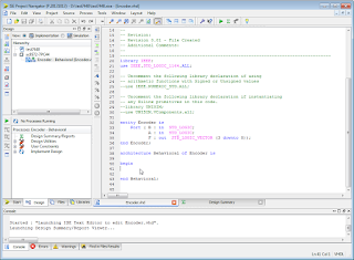
1.       ใช้ Xilinx ISE 14.4 ด้วยโปรแกรม VHDL ในการสร้าง 2 to 4 Line Encoder
ขั้นตอนดำเนินงานด้วย ISE 14.2


library IEEE;
use IEEE.STD_LOGIC_1164.ALL;
 
entity Encoder is
    Port ( B : in  STD_LOGIC;
           A : in  STD_LOGIC;
           F : out  STD_LOGIC_VECTOR (3 downto 0));
end Encoder;
architecture Behavioral of Encoder is
begin
               F <=        "0001" when (B='0' and A='0') else  
                               "0010" when (B='0' and A='1') else  
                               "0100" when (B='1' and A='0') else  
                               "1000" ;  
               
end Behavioral
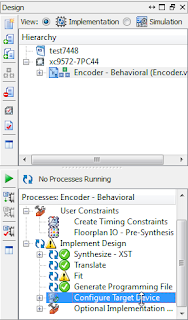
ขั้นตอนการดำเนินงานด้วย ISE 14.2 
New Project
Family            XC9500 CPLDs
Device            XC9572
Package        PC44

New Source
B          in
A          in
F          out       þ       3          0


Inplement All

Assigned Pin


Inplement All
Lode Program


Select file XXXX.jed
Opertation à Program
2.       ใช้ Xilinx ISE 14.4 ด้วยโปรแกรม VHDL ในการสร้าง 7_Segment Encoder


 library IEEE;
use IEEE.STD_LOGIC_1164.ALL;
-- Uncomment the following library declaration if using
-- arithmetic functions with Signed or Unsigned values
--use IEEE.NUMERIC_STD.ALL;
-- Uncomment the following library declaration if instantiating
-- any Xilinx primitives in this code.
--library UNISIM;
--use UNISIM.VComponents.all;

entity Encoder is
Port (      Inport : in STD_LOGIC_VECTOR (3 downto 0);
                        Outport : out STD_LOGIC_VECTOR (6 downto 0));
end Encoder;
architecture Behavioral of Encoder is
begin
Outport <= "1111110" when Inport ="0000" else
                        "0110000" when Inport ="0001" else
                        "1101101" when Inport ="0010" else
                        "1111001" when Inport ="0011" else
                        "0110011" when Inport ="0100" else
                        "1011011" when Inport ="0101" else
                        "1011111" when Inport ="0110" else
                        "1110000" when Inport ="0111" else
                        "1111111" when Inport ="1000" else
                        "1111011" when Inport ="1001" else
                        "1110111" when Inport ="1010" else
                        "0011111" when Inport ="1011" else
                        "1001110" when Inport ="1100" else
                        "0111101" when Inport ="1101" else
                        "1001111" when Inport ="1110" else
                        "1000111" ;
 end Behavioral;

3.       จากโปรแกรมนับขึ้น 4 บิตด้วย VHDL ทดสอบกับ LED Logic Monitor 4 ดวง ให้ปรับปรุงโปรแกรมนี้เพื่อนับแบบเลข 8 บิต ทดสอบร่วมกับ 7_Segment Encoder ที่สร้างขึ้นจากข้อ 2 การแสดงผลจะเริ่มจาก 00 – FF
VHDL Code - 4Bit Up Counter from 0000 to 1111
library ieee;
use ieee.std_logic_1164.all;
use ieee.std_logic_unsigned.all;

entity Counter is
            Port (   clk : in  STD_LOGIC;
                        reset : in  STD_LOGIC;
                        Output : out  STD_LOGIC_VECTOR (3 downto 0));
end Counter;

architecture Behavioral of Counter is
signal pre_count: std_logic_vector(3 downto 0);
begin
            process(clk, reset)
            begin
                        if reset = '1' then
                                    pre_count <= "0000";
                        elsif (clk='1' and clk'event) then
                                    pre_count <= pre_count + "1";
                        end if;
            end process; 
            Output <= pre_count;
end Behavioral;
 VHDL Code – 8Bit Counter from 00 to FF

#include <SPI.h>
#include "LedMatrix.h"
#include <Wire.h>
#include "ClosedCube_HDC1080.h"
#define NUMBER_OF_DEVICES 1
#define CS_PIN D8
LedMatrix ledMatrix = LedMatrix(NUMBER_OF_DEVICES, CS_PIN);
//Button D3
//SDA in HDC1080 D2
//SCl in HDC1080 D1
//CLK in MAX7219 D5
//DIN in MAX7219 D7
//CS in MAX7219 D8
ClosedCube_HDC1080 hdc1080;
void setup() {
  pinMode(D3, INPUT_PULLUP);
  Serial.begin(115200); // For debugging output
  ledMatrix.init();
  ledMatrix.setIntensity(15); // range is 0-15
  ledMatrix.clear();
  ledMatrix.commit(); // commit send buffer to the displays
  Serial.begin(9600);
  Serial.println("ClosedCube HDC1080 Arduino Test");
  hdc1080.begin(0x40);
  Serial.print("Manufacturer ID=0x");
  Serial.println(hdc1080.readManufacturerId(), HEX); // 0x5449 ID of Texas Instruments
  Serial.print("Device ID=0x");
  Serial.println(hdc1080.readDeviceId(), HEX); // 0x1050 ID of the device
}
int stat = 1;
void loop() {
  ledMatrix.clear();
  ledMatrix.commit(); // commit send buffer to the displays
  Send2MAX7129(4, 5, 0);
  Send2MAX7129(3, 6, 0);
  Send2MAX7129(2, 7, 0);
  Send2MAX7129(1, stat, 0);
  stat++;
  if(stat==5){
    stat=1;
  }
 

  delay(1000);
}
//=================================================== // ##SegPosition >> 87654321 ##SegData >> tabcdefg //===================================================
void Send2MAX7129(byte SegPosition, byte Value, bool dotDigit) {
  const static byte charTable [] =  { B01111110, B00110000, B01101101, B01111001, //
                                      B00110011, B00001110, B01001111, B00111101
                                    };
  Value = charTable[Value];
  if (dotDigit == 1) Value |= 0x80;
  digitalWrite(CS_PIN, LOW);
  SPI.transfer (SegPosition);
  SPI.transfer (Value);
  digitalWrite (CS_PIN, HIGH);
}
//=================================================== // ##SegPosition >> 87654321 ##SegData >> tabcdefg //===================================================
void SendData2MAX7129(byte SegPosition, byte SegData) {
  digitalWrite(CS_PIN, LOW);
  SPI.transfer (SegPosition);
  SPI.transfer (SegData);
  digitalWrite (CS_PIN, HIGH);
}

4.       ปรับวงจรนับเป็น Up-Down Counter 4 bit โดยมี สัญญาญ CU ควบคุมการนับ ทดสอบร่วมกับ 7_Segment Encoder ที่สร้างขึ้นจากข้อ 2 การแสดงผลระหว่าง 0 - F
·          C ควบคุมการนับและหยุดนับ             ถ้าเป็น 1 ให้นับต่อ          ถ้าเป็น 0 ให้หยุดนับ
·          U ควบคุมทิศทางการนับ                    ถ้าเป็น 1 ให้นับขึ้น          ถ้าเป็น 0 ให้นับลง

VHDL Code - 4Bit Counter with Control (0000 - 1111)
library ieee;
use ieee.std_logic_1164.all;
use ieee.std_logic_unsigned.all;
entity Counter is
        Port (       Clk                    : in  STD_LOGIC;
                        Enable              : in  STD_LOGIC;
                        UpDown           : in  STD_LOGIC;
                        Reset                : in  STD_LOGIC;
                        Output             : out  STD_LOGIC_VECTOR (3 downto 0));
end Counter;
architecture Behavioral of Counter is
signal pre_count: std_logic_vector(3 downto 0);
begin
            process(Clk, Reset, Enable, UpDown)
            begin
                        if Reset = '1' then
                                    pre_count <= "0000";
                        elsif (Clk='1' and Clk'event) then
                                    if Enable='1' then
                                                if UpDown='1' then
                                                            pre_count <= pre_count + "1";
                                                else
                                                            pre_count <= pre_count - "1";
                                                end if;
                                    end if;
                        end if;
            end process; 
            Output <= pre_count;
end Behavioral;

 VHDL Code – 4Bit Counter from 0 to F
library ieee;
use ieee.std_logic_1164.all;
use ieee.std_logic_unsigned.all;

entity Counter is
               Port (       Clk                         : in  STD_LOGIC;
                               Enable                    : in  STD_LOGIC;
                               UpDown  : in  STD_LOGIC;
                               Reset                       : in  STD_LOGIC;
                               Output                   : out  STD_LOGIC_VECTOR (6 downto 0));
end Counter;

architecture Behavioral of Counter is
signal pre_count: std_logic_vector(3 downto 0);
begin
               process(Clk, Reset, Enable, UpDown)
               begin
                               if Reset = '1' then
                                              pre_count <= "0000";
                               elsif (Clk='1' and Clk'event) then
                                              if Enable='1' then
                                                             if UpDown='1' then
                                                                            pre_count <= pre_count + "1";
                                                             else
                                                                            pre_count <= pre_count - "1";
                                                             end if;
                                              end if;
                               end if;
               end process; 
               Output <=  "1111110" when pre_count ="0000" else
                                                                            "0110000" when pre_count ="0001" else
                                                                            "1101101" when pre_count ="0010" else
                                                                            "1111001" when pre_count ="0011" else
                                                                            "0110011" when pre_count ="0100" else
                                                                            "1011011" when pre_count ="0101" else
                                                                            "1011111" when pre_count ="0110" else
                                                                            "1110000" when pre_count ="0111" else
                                                                            "1111111" when pre_count ="1000" else
                                                                            "1111011" when pre_count ="1001" else
                                                                            "1110111" when pre_count ="1010" else
                                                                            "0011111" when pre_count ="1011" else
                                                                            "1001110" when pre_count ="1100" else
                                                                            "0111101" when pre_count ="1101" else
                                                                            "1001111" when pre_count ="1110" else
                                                                            "1000111" ;
end Behavioral;


5.       ออกแบบ ALU(Arithmetic Logic Unit) โดยใช้ VHDL ให้มี Output F[3..0] และ Input A[1..0], B[1..0], C[2..0] กำหนดฟังก์ชันการทำงาน ดังนี้

C[2..0]
Logic Function

C[2..0]
Math Function
000
F= A

100
F = A plus B
001
F = A OR B

101
F = A minus B
010
F = A AND B

110
F = -A
011
F = A XOR B

111
F = A plus 1

 library IEEE;
use IEEE.STD_LOGIC_1164.ALL;
Use ieee.std_logic_unsigned.all; 
Use ieee.std_logic_arith.all; 
use IEEE.NUMERIC_STD.ALL;
entity Sample5 is
Port ( C : in STD_LOGIC_VECTOR (2 downto 0);
iA : in STD_LOGIC_VECTOR (1 downto 0);
iB : in STD_LOGIC_VECTOR (1 downto 0);
F : out STD_LOGIC_VECTOR (3 downto 0));
end Sample5;
architecture Behavioral of Sample5 is
signal pre: std_logic_vector(3 downto 0);
signal InA: std_logic_vector(3 downto 0);
signal InB: std_logic_vector(3 downto 0);
begin
InA(1 downto 0) <= IA(1 downto 0);
InB(1 downto 0) <= IB(1 downto 0);
process(C,IA,IB)
begin
if(C="000") then pre <= not InA;
elsif(C="001") then pre <= InA or InB;
elsif(C="010") then pre <= InA and InB; 
elsif(C="011") then pre <= InA xor InB;
elsif(C="100") then pre <= InA + InB;
elsif(C="101") then pre <= InA - InB;
elsif(C="110") then pre <= (not InA)+1;
else pre <= InA + 1;
end if ;
end process;
F <= pre;
end Behavioral
;

NI labview 2014

NI labview 2014 โปรแกรม LabVIEW ย่อมาจาก Laboratory Virtual Instrument Engineering Workbench โปรแกรมที่ พัฒนาขึ้นมาโดยใช้ LABVIEW ...